Electrical systems differ on the basis of:
The type of system earthing must be selected carefully as it essentially determines the behaviour and properties of the supply system. It is also a contributing factor to issues associated with system usage, such as:
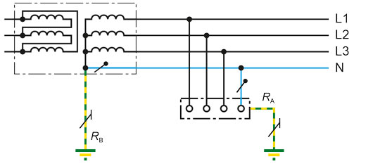
In TT systems, one point is connected directly to earth (functional earthing). The exposed-conductive parts of the electrical installation are connected to earth electrodes which are electrically isolated from the earth electrode for earthing the system.
Permissible protective devices:
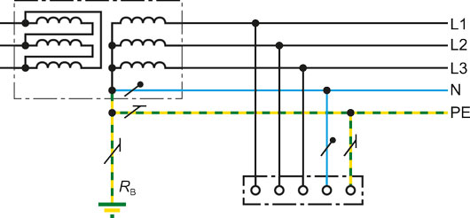
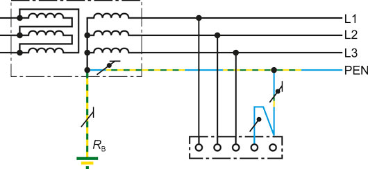
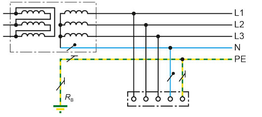
In TN systems, one point is connected directly to earth and the exposed conductive parts of the electrical installation are connected to this point via protective earth conductors.
There are three types of TN systems, differentiated on the basis of the arrangement of the neutral and protective earth conductors:
In IT systems, all live conductors are isolated from earth or one point is connected to earth via an impedance. On the occurrence of an insulation fault, therefore, only a small leakage current, essentially caused by system leakage capacitances, can flow. The upstream fuses do not trip. The voltage supply is also maintained in the event of single-pole direct earth faults.
The exposed-conductive parts of the electrical installation either
The following protective devices are permitted:
Characteristic features
| Type of supply system | Your benefits | Disadvantages |
| SELV or PELV (safety extra-low voltage or protective extra low voltage) | • No hazard potential on contact | • Limited power if deployment of equipment is to be cost-effective • Specific requirements on current circuits |
| Protective insulation | • Maximum level of safety • Can be combined with other types of system | • Double insulation of equipment • Only cost-effective for small loads • Insulating material pose fire hazard on thermal loads |
| IT system | • EMC friendly • Increased availability: 1st fault is simply reported Disconnection in the event of a 2nd fault • Low earth leakage current in small systems • Influence on neighbouring installations is reduced, this in turn makes earthing easier • Little technical effort for cable and conductor installation • Use of appropriate devices facilitates fault location | • Equipment has to be insulated universally for the voltage between external conductors. • An overvoltage protective device is required for N conductors • Potential problems with going offline on second earth fault |
| TT system | • EMC friendly • Protection is dependent on the system's short circuit power • Little technical effort for cable and conductor installation • Touch voltage can vary from one area to another • Can be combined with a TN system | • Only compatible with low power ratings due to the use of RCDs • Regular functional test required • Operational earthing is complex (≤ 2 Ω). • Equipotential bonding compulsory for every building |
| TN-C system | • Easy to set up • Low material expenses | • Not EMC friendly • Building stray currents and low frequency magnetic fields make the system incompatible for use in buildings housing information technology equipment • Risk to life and limb in the event of PEN break • Increased risk of electrical fires |
| TN-C-S system | • A cost-effective compromise for buildings which do not house information technology equipment. | • Not EMC friendly • Low-frequency magnetic fields possible |
| TN-S system | • EMC friendly • Low voltage rise in the healthy phases | • Increased safety engineering outlay for remote multiple infeeds • Risk of multiple earthing going unnoticed |
| Criterion | TT | TN-C | TN-S | IT |
| Safety of personens | *** | *** | *** | *** |
| Safety against fire hazard | *** | * | ** | *** |
| Safety for machine protection | *** | * | * | *** |
| Availability | ** | ** | ** | **** |
| Electromagnetic compatibility | ** | * | ** | *** |
| Maintenance | ** | **** | **** | *** |
| Installation | * | ** | ** | *** |
| Overall result | * 16 | * 14 | * 16 | * 22 |
| Name | Category | Size | Language | Timestamp | D-/B-Number |
|---|---|---|---|---|---|
| Product Overview ISOMETER®/ISOSCAN® | Product Overviews | 5.3 MB | EN | 2024/02/1616.02.2024 | |
| Why the IT System is Often the Best Choice for Power Supply Systems of All Types | Technical article | 3.0 MB | EN | 2019/07/1111.07.2019 | |
| Initial and Periodic Verification of IT Systems | Technical article | 621.5 KB | EN | 2020/03/0202.03.2020 | |
| High Availability for Reliable Operation in Waste Water Treatment Facilities | Technical article | 601.8 KB | EN | 2019/05/1313.05.2019 | |
| IT System Ensures Electrical Safety at the Munich Airport | Technical article | 284.0 KB | EN | 2019/05/1313.05.2019 | |
| The Stone Age Meets Modern Network Protection Technology | Technical article | 338.5 KB | EN | 2019/05/1313.05.2019 | |
| The Largest Photovoltaic System in Latin America | Technical article | 447.8 KB | EN | 2019/05/1313.05.2019 |
Products

Insulation monitoring device for inverter applications and large industrial plants

Insulation fault locator for localisation of insulation faults in main circuits
Insulation monitoring device for inverter applications and large industrial plants
Insulation fault locator for localisation of insulation faults in main circuits